Wiring Diagrams - Toyota Pickup Ignition System Circuit Diagrams

Posted by Blogger.com on Saturday, March 31, 2012

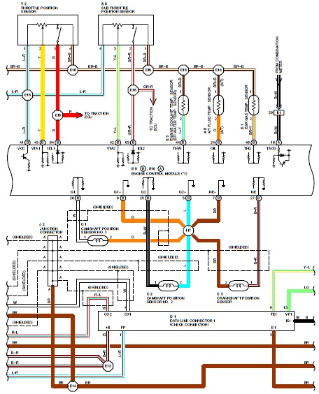
Wiring Diagrams - Toyota Pickup Ignition System Circuit Diagrams - here some diagrams for Ignition System on Toyota Pickup, The ignition system consists of battery, ignition switch, spark plug, cap and rotor, distributor, ignition coil with igniter, signal rotor, pickup coil, igniter and ECM. The ECM is programmed with data for optimum ignition timing under any and all operating conditions. Using data provided by sensors which monitor various engine functions (rpm, intake air volume, engine temperature, etc.) the microcomputer (ECM) triggers the spark at precisely the right instant.

Wiring Diagrams - Toyota Pickup Ignition System Circuit Diagrams

Wiring Diagrams - Toyota Pickup Ignition System Circuit Diagrams
Thanks for visiting Toyota Wiring Diagrams, i hope u find what u want in here. Find more Wiring Diagrams
More aboutWiring Diagrams - Toyota Pickup Ignition System Circuit Diagrams

Wiring Diagrams - Toyota Yaris Engine Immobilizer System

Posted by Blogger.com

Wiring Diagrams - Toyota Yaris Engine Immobilizer System here are some diagrams for Toyota Yaris Engine Immobilizer system, The 2007 Toyota Yaris is equipped with Engine Immobilizer System. It consists of transponder key coil/amplifier, unlock warning switch assembly, ECM and security indicator light. The engine immobilizer system is designed to prevent the vehicle from being stolen. This system uses a transponder key ECU that stores the key codes of authorized ignition keys. If an attempt is made to start the engine using an unauthorized key, the ECU sends a signal to the ECM to prohibit fuel delivery and ignition, effectively disabling the engine.

Wiring Diagrams - Toyota Yaris Engine Immobilizer System

Wiring Diagrams - Toyota Yaris Engine Immobilizer System
Thanks for visiting Toyota Wiring Diagrams, i hope u find what u want in here. Find more Wiring Diagrams
More aboutWiring Diagrams - Toyota Yaris Engine Immobilizer System

Electrical Wiring Diagrams - Toyota Highlander Hybrid Headlamps

Posted by Blogger.com

Electrical Wiring Diagrams - Toyota Highlander Hybrid Headlamps here are some diagrams to help u assembly Toyota Highlander Hybrid Headlamps. The following schematic shows a typical diagram of the 2006 Toyota Highlander Hybrid Headlamp Components Assembly and Parts.

Electrical Wiring Diagrams - Toyota Highlander Hybrid Headlamps

Electrical Wiring Diagrams - Toyota Highlander Hybrid Headlamps
Legend Electrical Wiring Diagrams - Toyota Highlander Hybrid Headlamps : 1) Headlamp assembly 2) Bolt 3) Grommet 4) Mount bracket 5) Headlamp bulb 6) High beam bulb 7) Signal lamp bulb 8) Socket 9) Repair bracket 10) Upper retainer 11) Lower retainer Thanks for visiting Toyota Wiring Diagrams, i hope u find what u want in here. Find more Wiring Diagrams
More aboutElectrical Wiring Diagrams - Toyota Highlander Hybrid Headlamps

Electrical Wiring Diagrams - Toyota FJ Cruiser Stop Light

Posted by Blogger.com

Electrical Wiring Diagrams - Toyota FJ Cruiser Stop Light here are some electrical wiring diagrams for Toyota FJ Cruiser, The 2007 Toyota FJ Cruiser stop light switch is a duplex system that transmits two signals: STP and ST1-. These two signals are used by the ECM to monitor whether or not the brake system is working properly. If the signals, which indicate the brake pedal is being depressed and released, are detected simultaneously, the ECM interprets this as a malfunction in the stop light switch and sets the DTC. Below schematic shows the Toyota FJ Cruiser Stop Light Switch Wiring Diagram.

Electrical Wiring Diagrams - Toyota FJ Cruiser Stop Light

Electrical Wiring Diagrams - Toyota FJ Cruiser Stop Light
Thanks for visiting Toyota Wiring Diagrams, i hope u find what u want in here. Find more Wiring Diagrams
More aboutElectrical Wiring Diagrams - Toyota FJ Cruiser Stop Light

Wiring Diagrams - Toyota 4Runner 1989 Fuel Pump Wiring Diagrams

Posted by Blogger.com

Wiring Diagrams - Toyota 4Runner 1989 Fuel Pump Wiring Diagrams here are some wiring diagrams for Toyota 4Runner Fuel Pump, The fuel pump wiring consists of: Electronic Fuel Injection Main Relay, Fuse EFI 15A, Ignition Switch, Engine Check Connector, Circuit Opening Relay, Fuel Pump, Switch, Clutch Start, Neutral Start Switch, Battery and Main Fuse 40A.

Wiring Diagrams - Toyota 4Runner 1989 Fuel Pump Wiring Diagrams

Wiring Diagrams - Toyota 4Runner 1989 Fuel Pump Wiring Diagrams
Thanks for visiting Toyota Wiring Diagrams, i hope u find what u want in here. Find more Wiring Diagrams
More aboutWiring Diagrams - Toyota 4Runner 1989 Fuel Pump Wiring Diagrams

Wiring Diagrams - Toyota Land Cruiser 1989 Cooling Fan Wiring Diagrams

Posted by Blogger.com

Wiring Diagrams - Toyota Land Cruiser 1989 Cooling Fan Wiring Diagrams here some wiring diagrams for Toyota Land Cruiser 1989, Herein you will get detailed description of electronic parts of the Cooling Fan system which include Battery, Fusible Link, Fuse, Ignition Switch, Cooling Fan Motor Relay, Manifold Temperature Sensor, Fan Motor, Ignition Relay, and Cooling Fan Relay Connector (cooling fan relay is located behind driver’s side kick panel while the ignition relay is under left side of instrument panel in relay panel).

Wiring Diagrams - Toyota Land Cruiser 1989 Cooling Fan Wiring Diagrams

Wiring Diagrams - Toyota Land Cruiser 1989 Cooling Fan Wiring Diagrams
Thanks for visiting Toyota Wiring Diagrams, i hope u find what u want in here. Find more Wiring Diagrams
More aboutWiring Diagrams - Toyota Land Cruiser 1989 Cooling Fan Wiring Diagrams

Wiring Diagrams - Toyota Tacoma Truck Starting System

Posted by Blogger.com

Wiring Diagrams - Toyota Tacoma Truck Starting System here are some wiring diagrams for Toyota Tacoma Truck, The starting system is the heart of the electrical system in a car. It consists of battery, starter motor, solenoid, ignition switch, and in some cases, a starter relay. starting system includes the battery, starter motor, solenoid, ignition switch, and in some cases, a starter relay. The following schematic shows the Toyota Tacoma Truck Starting System Wiring Diagram. The wiring diagram depicts the interconnection between the starting system parts/components which include ignition switch, clutch start switch, battery, starter motor, and starter relay. The starter motor drives the engine through a pinion gear that engages the ring gear on the flywheel.

Wiring Diagrams - Toyota Tacoma Truck Starting System

Wiring Diagrams - Toyota Tacoma Truck Starting System
Thanks for visiting Toyota Wiring Diagrams, i hope u find what u want in here.
More aboutWiring Diagrams - Toyota Tacoma Truck Starting System

Wiring Diagram - Toyota Celica 2000 Fuel Pump Control Circuit

Posted by Blogger.com

Wiring Diagram - Toyota Celica 2000 Fuel Pump Control Circuit - here are some wiring diagrams for Toyota Celica 2000 Fuel Pump Control Circuit The fuel pump control consists of: EFI main relay, circuit opening relay, fuel pump, ignition switch, battery, ECM and fuel pump. When the engine is cranked, current flows from terminal ST of the ignition switch to the starter relay coil and also to terminal STA of ECM. When the STA signal and NE signal are input to the ECM, Tr is turned ON, current flows to coil in the circuit opening relay, the relay switched on, power is supplied to the fuel pump and the fuel pump operates. While the NE signal is generated (engine running), the ECM keeps Tr ON (circuit opening relay ON) and the fuel pump also keeps operating.

Wiring Diagram - Toyota Celica 2000 Fuel Pump Control Circuit

Wiring Diagram - Toyota Celica 2000 Fuel Pump Control Circuit
More aboutWiring Diagram - Toyota Celica 2000 Fuel Pump Control Circuit

Wiring Diagrams - 2006 Toyota RAV4 Instrument Panel Relay Location and Layout

Posted by Blogger.com

Wiring Diagrams - 2006 Toyota RAV4 Instrument Panel Relay Location and Layout - here are some wiring diagrams for 2006 Toyota RAV4 Instrument Panel Relay Location and Layout Diagram.

2006 Toyota RAV4 Instrument Panel Relay Location and Layout Diagram

Wiring Diagrams - 2006 Toyota RAV4 Instrument Panel Relay Location and Layout

Legend of Wiring Diagrams - 2006 Toyota RAV4 Instrument Panel Relay Location and Layout :

1. Power Steering ECU
2. J/B No.3
3. Transponder Key ECU
4. J/B No.4
5. Tire Pressure Warning ECU
6. 4WD Control ECU
7. Airbag Sensor Assembly Center
8. Shiftlock Control ECU
9. A/C Amplifier
10. Transponder Key Amplifier
11. J/B No.5
12. J/B No.6
13. J/B No.7
14. Instrument Panel J/B Main Body ECU
More aboutWiring Diagrams - 2006 Toyota RAV4 Instrument Panel Relay Location and Layout

Wiring Diagrams : Toyota Camry Ignition System Wiring and Circuit

Posted by Blogger.com

Wiring Diagrams : Toyota Camry Ignition System Wiring and Circuit - here are some wiring diagrams for The Toyota Camry Ignition System comprises of engine control module (ECM), igniter, ignition coil, distributor and pickup coils. The ECM is programmed with data (rpm, intake air volume, engine temperature, etc.) for optimum ignition timing under all operating conditions. The igniter temporarily interrupts the primary current with the ignition signal (lGT signal) from the ECM and generates sparks at the spark plug. Below schematic depicts the Toyota Camry Ignition System Wiring and System Circuit. This correctly distributes high voltage to the spark plug of each cylinder in the specified ignition order.

Wiring Diagrams : Toyota Camry Ignition System Wiring and Circuit

Wiring Diagrams : Toyota Camry Ignition System Wiring and Circuit

To maintain the most appropriate ignition timing, the ECM sends a control signal so that the igniter sends current to the ignition coil and the spark plugs produce a spark.
More aboutWiring Diagrams : Toyota Camry Ignition System Wiring and Circuit

Wiring Diagrams - 1995 Toyota Supra Wiring Diagram

Posted by Blogger.com on Monday, March 19, 2012

Wiring Diagrams - 1995 Toyota Supra Wiring Diagram

This wiring diagram is applicable for 1995 Toyota Supra. This manual provides information on the electrical circuit installed on the vehicles by dividing them into a circuit for each system. The actual wiring of each system circuit is shown from the point where the power source is received from the battery as far as each ground point.

The wiring diagram manual is divided into 12 main sections which are Index and Introduction; How to Use this Manual; Troubleshooting (Describes the basic inspection procedures for electrical circuits); Abbreviation; Glossary of Terms and Symbols; Relay Location (Shows position of the Electronic Control Unit, Relays, Relay Block, etc. This section is closely related to the system circuit); Electrical Wiring Routing (Describes position of Parts Connectors, Splice points, Ground points, etc. This section is closely related to the system circuit); Power Source (Describes power distribution from the power supply to various electrical loads); System Circuit (Electrical circuits of each system are shown from the power supply through ground points. Wiring connections and their positions are shown and classified by code according to the connection method); Ground Points; Overall Electrical Wiring Diagram (Provides circuit diagrams showing the circuit connections).

Wiring Diagrams - 1995 Toyota Supra Wiring Diagram
More aboutWiring Diagrams - 1995 Toyota Supra Wiring Diagram

Wiring Diagrams - 2000 Toyota Celica Wiring Diagram

Posted by Blogger.com

Wiring Diagrams - 2000 Toyota Celica Wiring Diagram

Back in 1970, Toyota released the Celica line for the first time, targeted to be an alternative for other Toyota’s sportscar, the 2000GT.

The above schematic just an illustration for the 2000 Toyota Celica Electric System Circuit and wiring diagram. This file is divided into 3 parts, the engine control system wiring, overall wiring diagram, and starting and ignition system.

Wiring Diagrams - 2000 Toyota Celica Wiring Diagram
More aboutWiring Diagrams - 2000 Toyota Celica Wiring Diagram

Wiring Diagrams - 2000 Toyota Land Cruiser Prado Electrical Wiring Diagram

Posted by Blogger.com

Wiring Diagrams - 2000 Toyota Land Cruiser Prado Electrical Wiring Diagram

Please note that the above schematic is just an illustration for the Toyota Land Cruiser Prado Wiring Diagram. For complete circuit and schematic you can find and download on below link provided. This wiring diagram applies for 2000 Toyota Land Cruiser Prado series.

Herein you will find complete depiction of 2000 Toyota Land Cruiser Prado engine control electrical wiring diagram which cover: Air Conditioner System, Center Different Lock, ChargingCombination Meter, Condenser Fan, Cruise Control, ECT and A/T Indicator, Engine Control, Engine Immobilizer System, Glow Plug, Fuel Heater, SRS, Starting, VSC. There are also Connector Joining W ire Harness and W ire Harness diagram.

Wiring Diagrams - 2000 Toyota Land Cruiser Prado Electrical Wiring Diagram
More aboutWiring Diagrams - 2000 Toyota Land Cruiser Prado Electrical Wiring Diagram

Wiring Diagrams - 2004 Toyota Corolla Anti-Brake System Wiring Diagram

Posted by Blogger.com

Wiring Diagrams - 2004 Toyota Corolla Anti-Brake System Wiring Diagram

This Wiring Diagram applies for 2004 Toyota Corolla Anti-Brake System. Anti-Brake System (ABS) is a brake system designed to improve the operating ability and securing the stability of the vehicle by preventing the lock–up of the vehicle by controlling the wheel cylinder pressure of all the four wheels at the time of sudden braking.

When the wheels are locked–up, the solenoid inside the actuator is controlled by the signal from the skid control ECU with actuator, and the brake fluid in the wheel cylinder will flow through the reservoir and reduce the hydraulic pressure. While the ABS is in operation, as the skid control ECU with actuator always outputs the operation signal to the pump inside the actuator, and the brake fluid stored inside the reservoir will be sucked up by the pump inside the actuator and returned to the master cylinder.

Wiring Diagrams - 2004 Toyota Corolla Anti-Brake System Wiring Diagram
More aboutWiring Diagrams - 2004 Toyota Corolla Anti-Brake System Wiring Diagram

Wiring Diagrams - 2004 Toyota Corolla Air Conditioning System Wiring Diagram

Posted by Blogger.com

Wiring Diagrams - 2004 Toyota Corolla Air Conditioning System Wiring Diagram

This wiring diagram applies for 2004 Toyota Corolla Air Conditioning System. Here you will find brief explanation on Corolla Air Conditioning electrical system, for instance what is the condition on the lower speed operation of the AC system.


Current is applied at all times through the HEATER fuse to TERMINAL 5 of the HTR relay. When the ignition SW is turned on, the current flows through the GAUGE fuse to TERMINAL 2 of the HTR relay to TERMINAL 1 to TERMINAL 6 of the blower SW

Wiring Diagrams - 2004 Toyota Corolla Air Conditioning System Wiring Diagram
More aboutWiring Diagrams - 2004 Toyota Corolla Air Conditioning System Wiring Diagram

Wiring Diagrams - 1990 Toyota Supra Electrical Wiring Diagram

Posted by Blogger.com

Wiring Diagrams - 1990 Toyota Supra Electrical Wiring Diagram

This electrical wiring diagram provides information in the electrical system specification of the 1990 Toyota Supra. This manual is divided into 6 main sections which are Index and Introduction; How to Use this Manual; Abbreviation; Relay Location (shows position of the electrical control unit, relays, relay block, etc.this section is closely related to the wiring diagram sections); Parts List; and Electrical Wiring Diagram(provide circuit diagrams showing the circuit connections. Illustration of 1990 Toyota Supra Electrical System Wiring Diagram.

Wiring Diagrams - 1990 Toyota Supra Electrical Wiring Diagram
More aboutWiring Diagrams - 1990 Toyota Supra Electrical Wiring Diagram

Wiring Diagram - Toyota Anti-Lock Brakes Electrical Wiring Diagram Manual

Posted by Blogger.com

Wiring Diagram - Toyota Anti-Lock Brakes Electrical Wiring Diagram Manual


This Electrical Wiring Diagram Manual is applicable for Toyota Anti-Lock brakes system. Toyota Antilock Brake System (ABS) are integrated with the conventional braking system. They use a computer controlled actuator unit, between the brake master cylinder and the wheel cylinders to control brake system hydraulic pressure. This manual is divided into section which each section describe each parts of the Toyota Antilock Brake System.

Content: Fundamental ABS System, Tire Traction and ABS, Basic Operation, Types of Toyota ABS, System Components, Wheel Speed Sensor, Deceleration Sensor, Lateral Acceleration Sensor, Semiconductor Deceleration Sensor, Actuator, Solenoid Relay Control, Pump Motor Relay Control, and Wheel Speed Control.

Wiring Diagram - Toyota Anti-Lock Brakes Electrical Wiring Diagram Manual
More aboutWiring Diagram - Toyota Anti-Lock Brakes Electrical Wiring Diagram Manual

Wiring Diagrams - Toyota Tacoma Electrical

Posted by Blogger.com on Friday, March 16, 2012

Wiring Diagrams - Toyota Tacoma Electrical

The Toyota Tacoma is a compact pickup truck manufactured by the Toyota Motor Company since 1995. There were three engines available for the first generation of Tacoma, which are the 2.4 L four cylinder rated at 142 hp (106 kW) and 160 lb·ft (217 N·m) of torque, the 2.7 L four cylinder rated at 150 hp (112 kW) and 177 lb·ft (240 N·m) of torque, and the 3.4 L six cylinder rated at 190 hp (142 kW) and 220 lb·ft (298 N·m) of torque.


The following electrical wiring diagram apply for Toyota Tacoma (sorry that i don’t really know from what series and year model it is). But here you will get brief and complete information about detail electrical wiring diagram including power source, starting, ignition and charging system. Engine Control Diagram and Headlight Circuit are some of example of them.

Wiring Diagrams - Toyota Tacoma Electrical
More aboutWiring Diagrams - Toyota Tacoma Electrical

User Manual Toyota Electrical Wiring Diagram

Posted by Blogger.com

User Manual Toyota Electrical Wiring Diagram

This manual is applicable for Toyota Electrical Wiring Diagram. In this manual you will find descriptive information on how to use Toyota’s electrical wiring diagram or EWD for short. This book is not just a book of wiring diagram, but an information resource for anything electrical on the vehicle. Everything from connector ID and location to what circuit share splice point is included in this manual.


User Manual Toyota Electrical Wiring Diagram
More aboutUser Manual Toyota Electrical Wiring Diagram

Wiring Diagrams - Toyota Typical ABS Control Relay

Posted by Blogger.com

Wiring Diagrams - Toyota Typical ABS Control Relay

Toyota Antilock Brake Systems (ABS) are integrated with the conventional braking system. The ABS system helps stop a car in the shortest possible distance without wheel lockup while maintaining directional control. Below schematic illustrates the typical Toyota ABS Control Relay Wiring Diagram. The motor relay switches voltage to the pump motor. The solenoid relay switches voltage to the actuator solenoids.


The ABS control relay consists of: fuse box, battery, ABS control relay, ABS ECU, ABS Actuator, and motor relay.

The ABS ECU senses the rotational speed of the wheels as well as the vehicle speed based on signals from the wheel speed sensors. The ECU then judges the slip condition between the wheels and the road surface by monitoring the change in the wheel’s rotational speed during braking.

Wiring Diagrams - Toyota Typical ABS Control Relay
More aboutWiring Diagrams - Toyota Typical ABS Control Relay